

The Conducted Emission test is usually also used as a harassment voltage test, as long as there are power line products involved, including many DC-powered products. In addition, the signal/control line also has conductive emission requirements in many standards. Usually used disturbance voltage or disturbance current limit (there is a mutual conversion relationship between), the insertion loss test in the luminaire (indicated directly in dB) also belongs to the conduction test category.
1. Conducted emission test standards:
CISPR22 (ITE), CISPR14-1 (Home Appliances and Tools), CISPR13 (AV), CISPR15 (Luminaires), CISPR11 (ISM), and other products and product standards are test methods that cite the above standards. Most of them refer to CISPR22.
2. Conducted emission test method:
1) Conducted emission test equipment and equipment: receiver, LISN (Line Impedance Stabilization Network, or AMN Artificial Power Network)
(combination), analog hands, passive voltage probes, current probes (CDNs for use with current probes, capacitive voltage probes), DIA (intermittent interference analyzers to test intermittent interference in CISPR14-1), test insertions Loss of a set of equipment, etc. Of course, PC is also indispensable, I heard that foreign senior engineer is directly measured manually by the receiver, Khan one.
The receiver and DIA are required to follow the requirements of CISPR16-1-1, and other auxiliary equipment must follow the requirements of CISPR16-1-2.
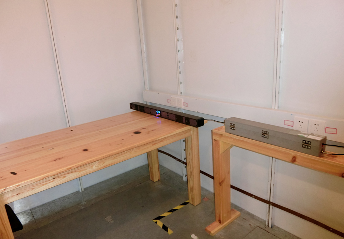
2) Conducted emission test arrangement: sub-desktop and floor-standing, desktop equipment from the LISN 80cm, 40cm from the ground plate (the grounding plate here can be a horizontal grounding plate, can also be the vertical grounding wall of the shielded room), floor-standing equipment from Ground plate distance varies according to different standards. CISPR14-1,15 is 10cm +/- 25%, 13 is up to 12mm, 22 is up to 15cm, there is no clear distance in 11 and only the need Separate the ground plate from the insulation material. The arrangement of auxiliary equipment is also different from the test standard. The auxiliary equipment in CISPR22 is 10cm away from the main equipment, and the interconnection between them is at least 40cm away from the ground plane. Holding a Class II device requires a simulator. Self-ballasted fluorescent lamps in CISPR15 need to be housed in an auxiliary tapered metal cover.
The test layout is given in a very intuitive layout diagram in different standards, at a glance, but it is not clear to describe it, huh, huh.
3) Conducted emission test frequency band: Mostly 150kHz-30MHz, CISPR15 is the exception (disturbance voltage 9kHz-30MHz, insertion loss 150kHz-1, 605kHz).
4) Conducted emission test limits: With different standards, different product categories (Group 1/2, Class A/B) and different limits.
5) Conducted emission test process:
a) AC/DC power supply disturbance voltage: this is the most common. Connect the power plug to the LISN. The RF input of the receiver is connected to the RF output of the LISN (may insert an RF attenuator or pulse limiter in the middle) to switch the LISN. The L/N switch selects the test mode power line common mode disturbance voltage.
b) Intermittent interference: CISPR14-1 and some standards that cite CISPR14-1 have requirements. Intermittent interference analyzers are often used in conjunction with LISN measurements. The standard also allows a combination of oscilloscope and receiver to be used instead. The oscilloscope observes the duration of the disturbance and the receiver observes the amplitude level of the disturbance.
c) Load disturbance voltage: CISPR14-1, CISPR15 and CISPR11 requirements. Use a passive voltage probe to strip off the load line that needs to be tested. Use the probe directly with the receiver to measure the disturbance voltage of the load wire terminal to ground.
In addition, if the rated current of the device is too large and no suitable LISN is available, the voltage probe can be used to measure the disturbance voltage at the power supply.
d) Communication line disturbance voltage/disturbance current: mentioned in CISPR22. There are different test methods for different types of communication lines. Annex C is described in detail. Annex F has analysis of advantages and disadvantages of various methods. Mainly rely on different combinations of current probe and CDN, 150 ohm earth resistance, capacitive voltage probe to test different types of communication cables. The prerequisite for guarantee is that the impedance of the test cable to ground is 150 ohms. The result can be expressed directly with the disturbance current dBuA, or it can be converted into the disturbance voltage dBuV, the conversion impedance is 150 ohms, which is a difference of 44 dB between the two values.
e) Insertion loss: mentioned in CISPR15. Use the RF sine wave generator to obtain the value of the insertion loss through the balun, the analog lamp, the LISN, and finally the comparator to measure the comparison voltage.
3. Conducted emission test results to determine:
This is simple, and the measured value (QP/AV) of the receiver detector is compared with the limit line respectively and is lower than the limit line PASS, which is higher than FAIL.
4. Conducted emission test notes:
Because the conduction test is a common mode disturbance measurement on the ground, the key is on the test layout. The layout is OK with the receiver, and the difference in the layout will cause the results to pass in and out.